VTTC (Vacuum Tube Tesla Coil) WIP
I’ve wanted for a long time to have a go at building a Vacuum Tube Tesla Coil. With so many choices of vacuum tubes I’m going to start with the relatively common and cheap 811A triode vacuum tube, as far as I’m aware though any transmitting tube with a plate dissipation of a few hundred Watts will work.
Why Build a VTTC?
Vacuum tube Tesla coils occupy a unique niche in the world of high voltage experimentation. Unlike their spark gap ancestors or solid-state successors, VTTCs produce nearly silent, sword-like streamers that have a distinctive character all their own.
A bit like a Nixie tube clock there is also something deeply satisfying about watching the orange glow of heated filaments inside those glass envelopes, it connects you to an earlier era of electronics while still producing impressive results.
Compared to modern DRSSTCs (Dual Resonant Solid State Tesla Coils), VTTCs are considerably simpler to build. A poorly wired solid-state coil can destroy expensive MOSFETs in milliseconds, sometimes explosively. Vacuum tubes, by contrast, are far more forgiving of construction errors and much easier to replace when things go wrong. Given the constraints of where I live it is also preferable to have something with slightly quieter operation than a spark gap Tesla coil.
How a VTTC Works
At its core, a VTTC is a self-oscillating Class C Armstrong oscillator. The vacuum tube acts as a high-frequency switch, controlling current flow through an LC tank circuit (formed by the primary coil and tank capacitor) that drives the secondary at its resonant frequency.
The feedback coil, wound near the primary, samples the oscillating magnetic field and applies it to the tube’s grid. This feedback sustains oscillation at the secondary’s natural resonant frequency. The grid leak resistor and bypass capacitor set the bias conditions, keeping the tube conducting for less than 50% of each cycle-hence “Class C” operation.
When tuned properly, the primary circuit oscillates at the same frequency as the secondary coil’s resonance, causing energy to transfer efficiently and build up voltage at the topload until it breaks down the surrounding air as visible streamers.
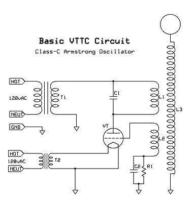 Credit to Steve Ward at https://www.stevehv.4hv.org/VTTCfaq.htm for the schematic
The 811A Tube
The 811A is an excellent choice for a first VTTC build. Originally designed as an RF power amplifier for amateur radio, it’s readily available, inexpensive (around $50 new), and well-documented.
Key specifications:
- Filament voltage: 6.3V at 4.0A
- Maximum plate voltage: 1500V (though many push them to 2kV with a microwave oven transformer)
- Plate dissipation: 65W (ICAS rating)
- Maximum plate current: 175mA
- Amplification factor: 160
- Base type: Medium 4-pin ceramic
Based on what I’ve seen online a single 811A can produce around 4-5 inch streamers, while a dual-tube configuration based on Steve Ward’s popular VTTC1 design can achieve considerably more. The 811A runs well at MOT (microwave oven transformer) voltages around 2kV, making the power supply straightforward.
One note on tube orientation: if using original RCA 811As, they can be mounted horizontally with proper pin orientation (check the datasheet). Modern Chinese imports are less robust and generally should be kept vertical to prevent grid sag over time.
Requirements
For this build few parts are needed, most obviously I will need the vacuum tube, as well I will require the following:
Power Supply
- Variac (variable autotransformer): This will allow me to gradually turn up the voltage during tuning and testing, as well as preheating the tube allowing its filament to heat up before applying the high plate voltage. As the 811A has a thoriated tungsten filament it needs time to reach its optimal operating temperature of 800-1000°C. Additionally, running the tube cold may increase the risk of cathode flashover which can damage the tube.
- Microwave oven transformer (MOT): This provides the high voltage (2kV AC) supply, which can be used directly or rectified.
- Rectifier diodes: Optional, if running DC plate supply. Many VTTCs run fine on raw AC from the MOT.
- Filter capacitors: To smooth the DC supply if using a rectified supply. These would be high voltage electrolytic capacitors rated appropriately.
Filament Supply
- 6.3V transformer: Capable of about 4A for a single tube (8A for dual tubes). A rewound MOT may suffice if I can’t find a dedicated transformer. The filament circuit floats at high voltage, so insulation is critical.
- Soft-start circuit (optional): A stepped heater warm-up (first through a ballast resistor, then direct) extends tube life by reducing thermal shock to the filament.
RF Tank Circuit
- Tank capacitor: 1-2nF rated for at least 15-30kV. High-quality doorknob capacitors or mica transmitting capacitors are ideal. The cheap Chinese doorknobs can fail at higher power levels.
- Primary coil: 15-25 turns of 12-14 AWG wire on a form slightly larger than the secondary. Stranded or solid wire both work.
- Feedback coil: 10-16 turns of smaller gauge wire (24 AWG magnet wire works), wound above or below the primary.
Secondary and Topload
- Secondary coil: Typically wound on 3” PVC pipe with 800-1600 turns of 24-28 AWG magnet wire. Seal with polyurethane or varnish.
- Topload: A smooth sphere or toroid provides capacitance and shapes the electric field. A polished metal bowl, spun aluminium toroid, or even stacked HDD platters can work for smaller coils.
Control and Safety
- Grid leak resistor: Typically 1-10kΩ, sometimes using light bulbs (100W/230V) which provide visual feedback on grid current.
- RF bypass capacitor: Small ceramic capacitor (1-10nF) between feedback coil and ground.
- Staccato controller (optional): Interrupts the filament circuit to produce pulsed, sword-like arcs rather than continuous streamers. Helps keep tubes cool during extended operation.
Design Calculations
The following equations, originated by John Freau and documented in Steve Ward’s VTTC FAQ, provide starting points for component selection.
Tube Impedance
For a Class C oscillator with AC plate supply:
1
R = V / (4 × I)
Where V is plate voltage and I is maximum plate current. For a dual 811A setup at 2kV:
1
R = 2000 / (4 × 0.35) = 1428Ω
Tank Circuit Q
A Q factor between 10 and 20 is ideal. Lower Q means less tube efficiency but easier coupling. Higher Q means more tank losses but potentially better performance once tuned.
Resonant Frequency
The secondary’s resonant frequency depends on its inductance and self-capacitance plus topload capacitance. Aim to match the primary LC circuit to this frequency.
Safety Considerations
Tesla coils are extremely dangerous. The voltages and currents involved can kill. A few critical points:
- The primary circuit is the most lethal part. While the high-frequency secondary output relies on skin effect and is relatively (though not completely) safe, the 50/60Hz MOT supply will stop your heart.
- Always discharge capacitors before touching any primary circuit components. Use a grounded discharge stick with a high-wattage resistor.
- Never adjust the coil while powered. This seems obvious, but excitement leads to mistakes.
- Use a proper RF ground. A separate ground rod for the coil prevents interference with household wiring and electronics.
- Work with a buddy when possible, and keep one hand in your pocket when near energised equipment.
- Establish a clear perimeter around the operating coil, at least 10 feet beyond maximum arc reach.
- Ventilate your workspace. Tesla coil streamers produce ozone and nitrogen oxides which are harmful in enclosed spaces.
- Protect nearby electronics. The RF interference from a VTTC can damage computers, phones, and other sensitive equipment even if they’re not directly struck.
Construction Notes
[To be continued with build documentation, photos, and results…]
Resources
- Steve Ward’s VTTC FAQ and designs: stevehv.4hv.org
- High Voltage Forum VTTC section: highvoltageforum.net
- Kaizer Power Electronics VTTC builds: kaizerpowerelectronics.dk
This is a work in progress. Check back for updates as the build progresses.